timer-V4 Delay Timing Relay Module 12V LED Display

17,00  με ΦΠΑ

Άμεσα Διαθέσιμο. Παράδοση 1-3 Εργάσιμες

SKU 77700265 Κατηγορίες , , ,

ΑΜΕΣΗ ΑΠΟΣΤΟΛΗ

Αυθυμερόν αποστολή για διαθέσιμα προϊόντα

ΜΕ ΚΑΡΤΑ

Πληρωμή με χρεωστική ή πιστωτική κάρτα

ΜΕΤΑΦΟΡΑ

Πληρωμή με τραπεζική μεταφορά

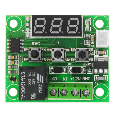
The delay timing relay module is equipped with a high-performance 8-bit microprocessor, and also has a 3-digit highlight digital tube onboard that can display the timing time in real-time. This module can be used to control solenoid valves, motors, light strips, and product aging. Tests and many other occasions.
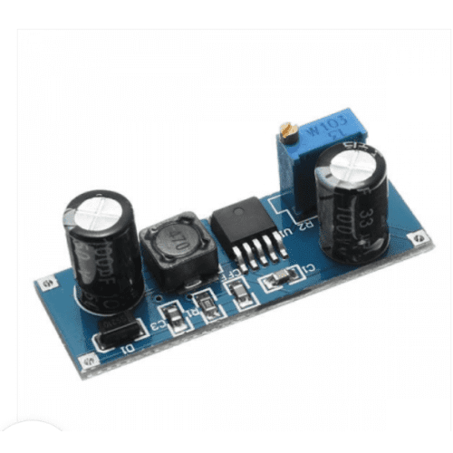
Note: The voltage should not exceed 20V as much as possible, because the linear voltage regulator efficiency is low, the voltage difference is large, the temperature will be high, and the heat dissipation may be bad.

Features

  1. Wide voltage power supply 5~30V;
  2. The interface is clear and simple, powerful, easy to understand, and almost meets all your needs;
  3. One-button emergency stop function (STOP button), with reverse connection protection, no burn when reverse connection;
  4. Different OP, CL, LOP parameters can be set, these parameters are independent of each other and saved separately;
  5. All set parameters are automatically saved when power is off;
  6. 0.1 second (small) ~ 999 minutes (large) continuously adjustable;

Hardware introduction and description

  1. Board size: 65*34mm
    Weight: 25g
  2. Interface introduction
  • Product parameters
    1): Working voltage: 5–30V (anti-reverse connection)
    2): Trigger signal source: High-level trigger (3.0V-24V) The signal ground and the system ground is not in the same ground to improve the anti-interference ability of the system (also can be short-circuited to the common ground)
    3): Output capacity: can control equipment within DC 30v 5A or AC 220v5A
    4): Quiescent current: 20mA Working current: 50mA
    5): Service life: more than 100,000 times; size: 65*34*17mm
    6): With optocoupler isolation, enhanced anti-interference ability, industrial-grade circuit board, set parameters are always remembered after power failure.
  • instructions for use
    1). working mode
    P1: After the signal is triggered, the relay is turned on for OP time, and then turned off; within OP time, the following operations
    P1.1: The signal is invalid when triggered again;
    P1.2: The signal is triggered again to re-timing;
    P1.3: The signal triggers the reset again, the relay is disconnected, and the timing stops;
    P2.1: Give the trigger signal, after the relay is turned off for CL time, the relay is turned on for OP time, after the timing is completed, turn off the relay;
    P3.1: Give the trigger signal, after the relay is turned on for the OP time, the relay is disconnected for CL time, and then the above actions are cycled, the signal is given again in the cycle, the relay is disconnected, and the timing stops; the number of cycles (LOP) can be set;
    P3.2: There is no need to trigger the signal after power-on, the OP time when the relay is on, and the CL time when the relay is off, the above actions are cycled; the number of cycles (LOP) can be set;
    P4.1: Signal holding function If there is a trigger signal, the timer is cleared, and the relay remains on; when the signal disappears, the relay is disconnected after timing OP; during the timing, there is another signal, and the timer is cleared;
    2). Select the timing range
    1) Timing range: 0.1 seconds (minimum) to 999 minutes (maximum) continuously adjustable.
    2) How to choose the timing range:
    After setting the parameter value in the mode selection interface, short press the STOP key to select the timing range; XXX. The decimal point is in the ones place, and the timing range: is 1 second to 999 seconds XX.X The decimal point is in the tens places, and the timing range is:
    0.1 seconds to 99.9 seconds X . X .X. All decimal points are on, timing range: 1 minute to 999 minutes For example if you want to set OP to 3.2 seconds, move the decimal point to the tens place, and the digital tube will display 03.2. Parameter description: OP on time, CL off time, LOP cycle times (1—999 times, ” — “means infinite loop)
    These parameters are independent of each other, but each mode shares these parameters. For example, when the on-time OP is set to 5 seconds in P1.1, the user wants to switch to P1.2 mode, then enter P1.2 to set the corresponding parameters, OP will also be 5 seconds;
    In the main interface (display 000), short press the SET button, it will display OP (CL, LOP) and the corresponding time XXX; If there is only OP in the mode (such as mode P1.1, P1.2, P1.3) time, then short press the SET key, only OP and the corresponding time will be displayed; If there are OP, CL, LOP in the mode (such as mode P3.1, P3.2), short press the SET key will display OP and the  corresponding time, CL and the corresponding time, LOP and the corresponding times;
    After setting the mode, you can easily view the parameters set in the current mode by
    short pressing the SET button on the main interface, which is very convenient!
  • Set parameters
    1) In the main interface, “press and hold the SET button for 2 seconds and then release” to enter the mode selection interface and select the mode to be set by short pressing the UP and DOWN buttons (P1. 1~P4. 1);
    2) After selecting the mode to be set (for example, P3.2), short press the SET button to set the corresponding parameters, then the parameters to be set will flash (OP on time, CL off time, LOP cycle times (“– -“Stands for unlimited cycles)), adjust the parameter value through UP and DOWN, support long press (rapid increase or decrease) and short press (increase or decrease by 1 unit); after setting the parameter value, short press the STOP button To select the position of the decimal point, select the timing range (corresponding time from 0.1 seconds to 999 minutes); Short press the SET key to set the next parameter of the current model, the process is the same as above;
    3) After setting the parameters of the selected mode, press and hold the SET button for 2 seconds and then release it, and then return to the main interface. The parameter setting is successful and very simple!
    After setting the parameters of the selected mode, press and hold the SET button for 2 seconds and then release it. The currently set mode will flash and then return to the main interface. The parameter setting is successful and very simple!
    Mode selection interface: Long press the SET button to enter, after the setting is completed, long-press the SET button to exit and return to the main interface, very simple!
  • STOP button function
    ON: The relay is allowed to conduct during OP conduction time;
    OFF: The relay is forbidden to conduct and is always off; short press the STOP button on the main interface to switch between ON and OFF, and then return to the main interface.
    (This function is an emergency stop function, one key to open and close the relay)